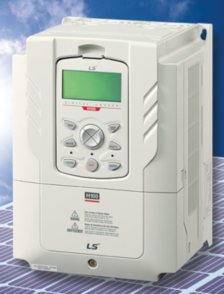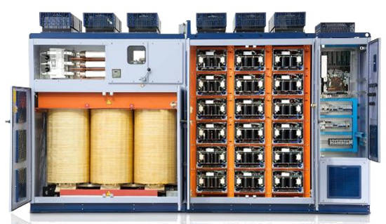

Thanks to this, among other benefits, an improvement in energy efficiency, a reduction in mechanical wear, and a better adaptation of the production process to variable load demands are achieved.
In addition to optimizing energy consumption, frequency converters typically incorporate numerous built-in protection functions (such as overcurrent, overvoltage, overload, and short-circuit protection) and diagnostic capabilities that increase equipment reliability. For these reasons, they are ubiquitous in modern industry: from pumps and fans to process machinery and automated production lines. Their proper engineering and safe integration with control systems are crucial for ensuring both performance and operational safety.
What is a variable frequency drive (VFD) and how does it work?
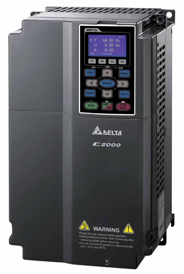
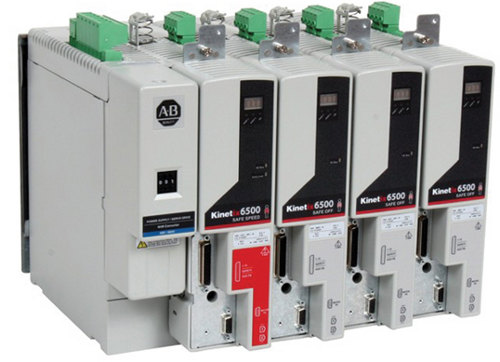
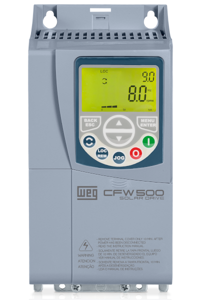
VFDs operate on the principle that the synchronous speed of an alternating current (AC) motor is determined by the supplied AC frequency and the number of poles in the stator. A VFD (Figure 1) integrates several stages: rectification, filtering, and an inverter stage that generates variable-frequency AC. Simply put, the AC mains power is converted to direct current (DC) by a rectifier; this DC is then conditioned by filtering and capacitors, and finally, an inverter generates an AC signal with controlled frequency and amplitude. By adjusting the frequency and output voltage, the speed and torque of the AC motor are regulated. VFDs also incorporate digital control systems (microcontrollers, FPGAs, etc.), sensors, and communication links (CAN, SPI, I²C, etc.) that manage the control logic of the inverter's power switches, protection devices, and external communication.
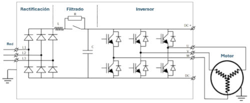
Figure 1: General schematic diagram of the power circuit of a frequency converter.
It is worth noting that, although in the context of a frequency converter we refer to the inverter stage as the part that converts DC to AC within the device, there are inverters designed as standalone units that are widely used outside the field of motor control. Common examples include grid-tie inverters in photovoltaic installations, inverters in battery storage systems and UPS systems, converters used in microgrids and distributed generation, and power inverters in electric traction. These inverters share similar switching principles and isolation challenges with the inverter stage of the frequency converter.
Why is electrical isolation necessary in a frequency converter or inverter?
During inverter operation, power switches (IGBTs) perform very high-speed switching, generating high-frequency harmonics, common-mode coupling, and other undesirable interference phenomena. These phenomena lead to a range of problems, including malfunctions in control electronics, signal distortion, communication interruptions, and inaccuracies in measuring instruments. Furthermore, power sections handle voltages that can reach hundreds or thousands of volts, making it crucial to prevent this high voltage from reaching the low-voltage control circuit and endangering components and personnel.
Galvanic isolation between the power and control sections is essential: it protects personnel and electronics from dangerous voltages, breaks ground loops that induce noise due to potential differences between earths, and improves immunity to transients (CMTI), ensuring the fidelity of control and sampling signals.
Currently, implementing proper isolation is not merely an aesthetic choice, but a fundamental design practice for achieving robust, reliable, and safe systems. As a key device capable of guaranteeing stable signal transmission under electrical isolation, the digital isolator has become a central component in the market.
Digital isolator: how to protect the safe operation of the inverter?
With the continuous development of modern industry towards high precision and energy efficiency, the digital isolator has become a key bridge connecting weak control with strong power in the inverter.
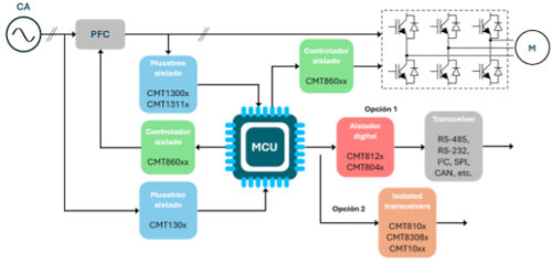
Figure 2: Schematic diagram of a typical electrical isolation circuit of an inverter.
As shown in Figure 2, in HOPERF's proposed electrical isolation scheme for inverters, the CMT860xx series isolated gate drivers and other HOPERF isolated drivers can be used between the system's master microcontroller and the IGBT power switches. These drivers effectively prevent high voltages from reaching the control side and damaging sensitive components. They also amplify the PWM (pulse-width modulation) signals to provide the necessary conduction current and meet the high-frequency switching requirements of the wide-bandwidth semiconductors. Furthermore, they incorporate fault protection mechanisms to ensure efficient and reliable inverter operation.
Isolated sampling circuits, such as the CMT130x series ADCs, can be used between the microcontroller and the high-voltage bus. This prevents the risk of high bus voltage reaching the control circuit and effectively suppresses noise, while simultaneously sampling analog signals (e.g., bus voltage and current), providing high-precision digital sample data to the microcontroller and significantly improving system reliability.
Standard digital isolators from the CMT812x and CMT804x series can also be placed between the master microcontroller and the serial buses (RS-485, SPI, I²C, etc.), eliminating ground loops and preventing noise from coupling to the communication link through ground or signal lines, thus ensuring stable data communication. Another viable option for communication is to use HOPERF's isolated transceivers: CMT810x, CMT8308x, CMT10xx, etc.
With industrial automation and the transition to more efficient and sustainable manufacturing, the digital isolator is emerging as an essential component for ensuring that power electronics operate safely, stably, and with low power consumption. Development trends point toward increasingly integrated, lower-power, and higher-performance solutions.